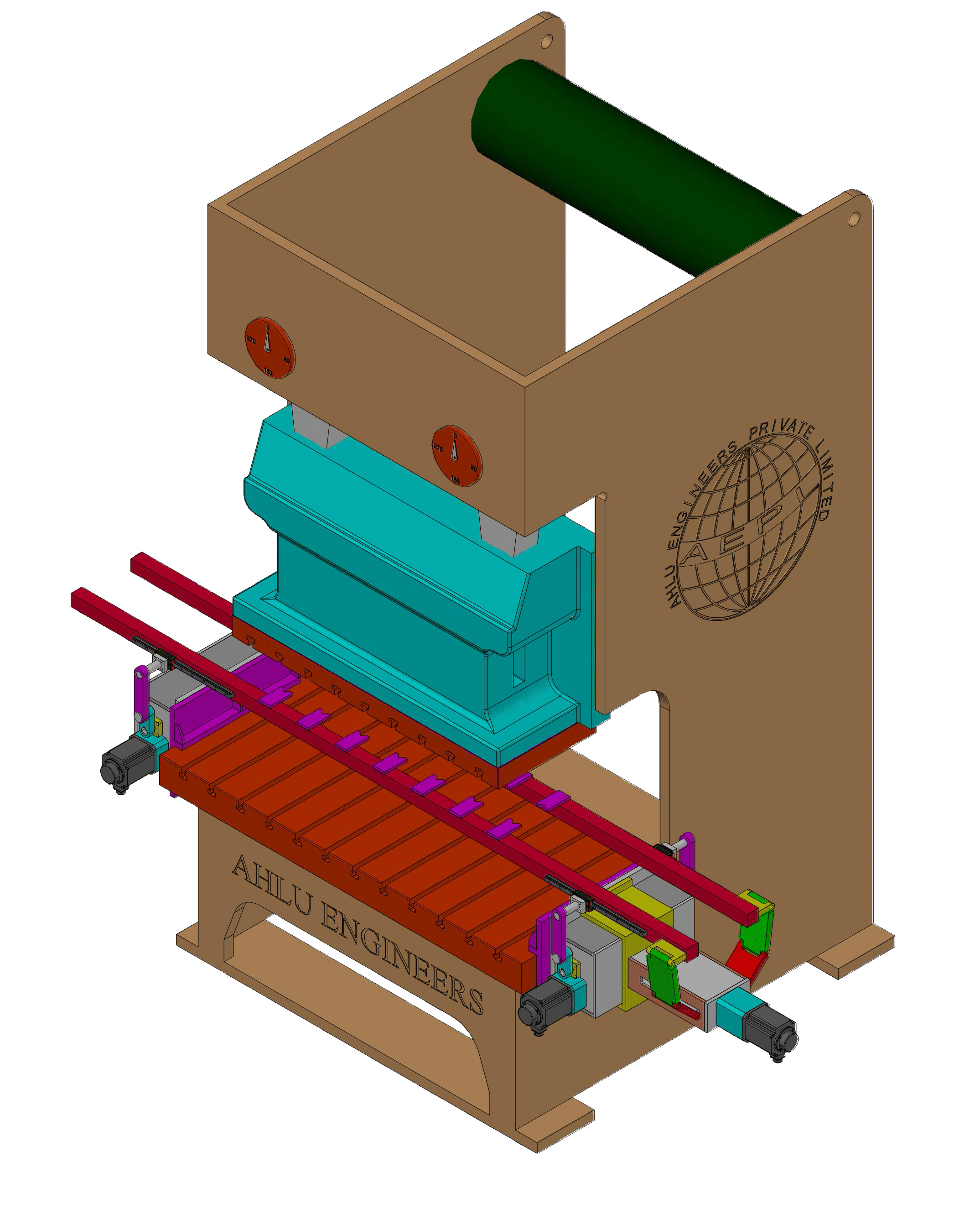
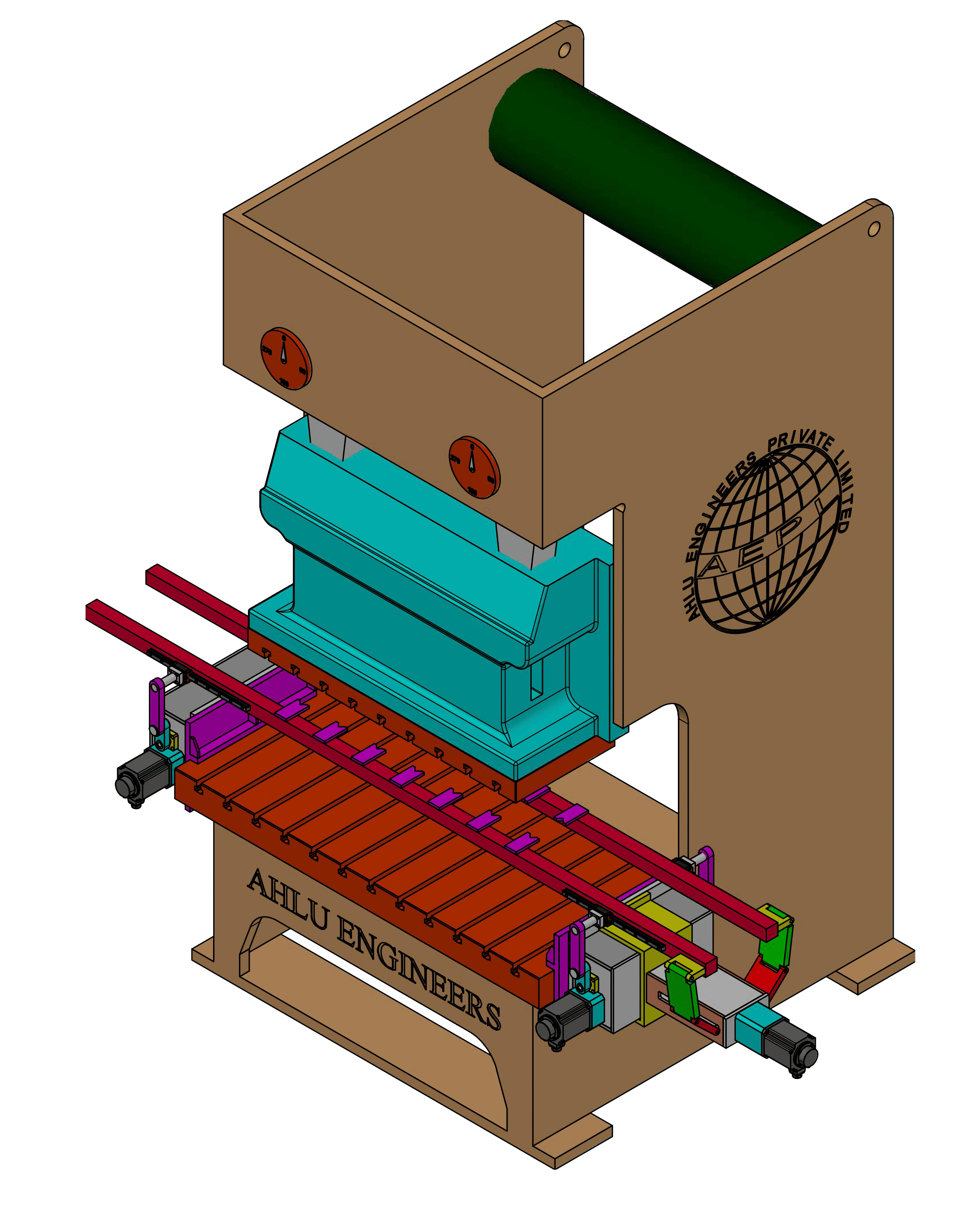
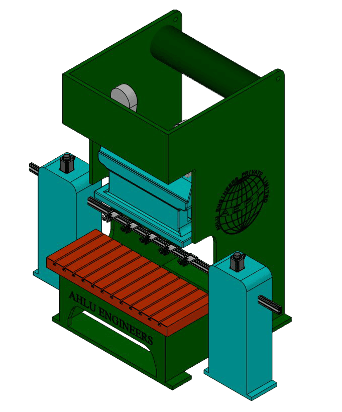
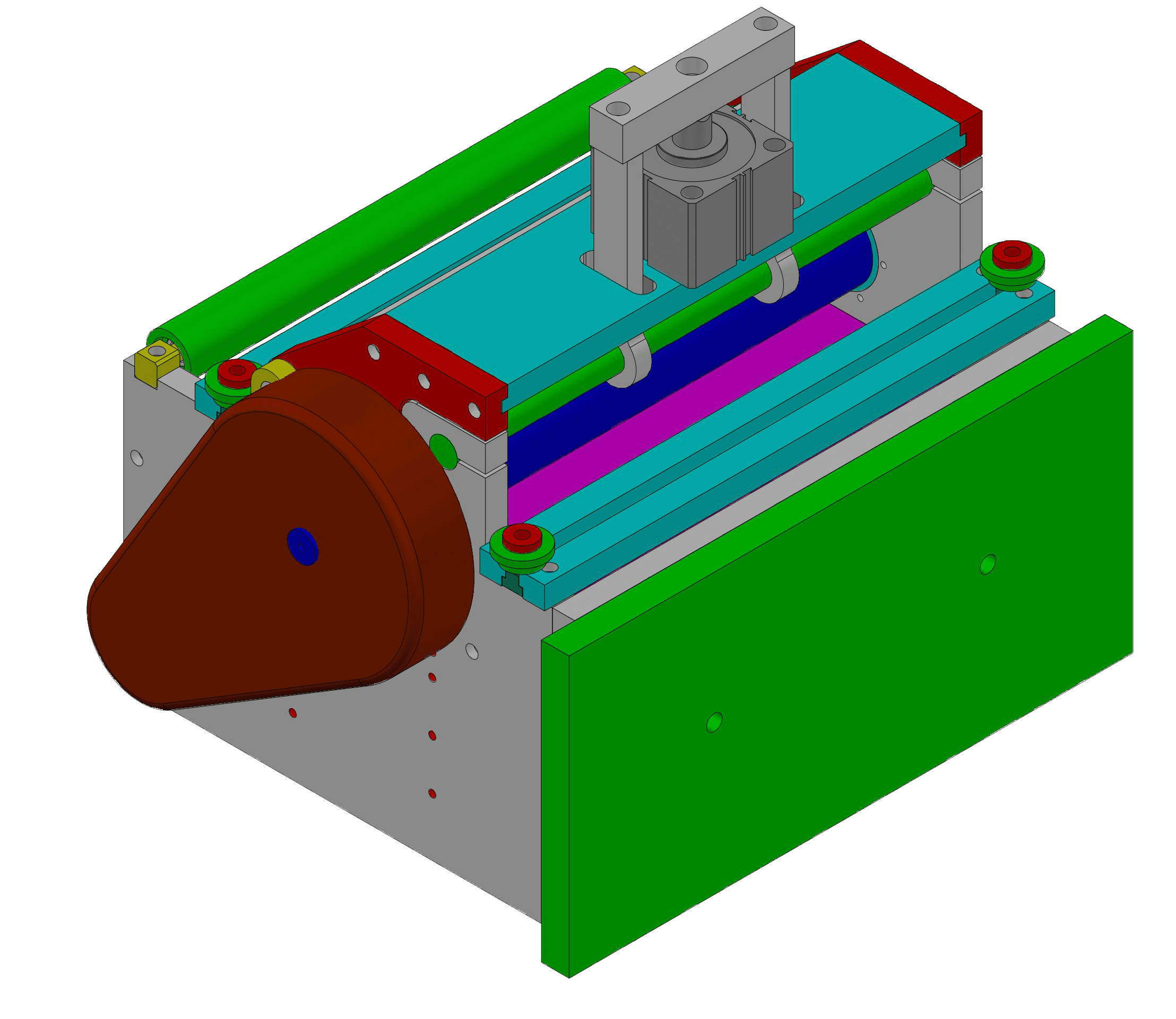
Ahlu Servo Transfer 3 Axis Double Bar type- AST3AII
Customized system designed only to achieve Speedy transfers in 3 Servo Axis for Z Axis draw/ Guided insertion based components. This Servo programmable transfer system drives a transfer unit with the help of a Double bar mechanism. Three variants of AST3AII series are available so that you can select a transfer pitch appropriate for your purpose
Common Characteristics of Two Bar System
- Each Servo Axis is operated with high accuracy with the help of Precision Servos.
- To Protect Tooling and Machine, each system is by-default comes with mis-feed, die-stuckage & Jamming detection feedbacks are taken in each process cycle to provide required safety.
- The Position Synchronization is performed with the help of Rotary Encoders which connects to the crankshaft of the press. All the transfer axes are driven by servo motor and run synchronously with the press.
- Along with Encoders, Transfer System Controller stays in-continuous communication with press PLC along with the Additional Hard Sensors mounted on output shaft via Rotary cam box to reduce any accidental risk in case of Encoder failure.
- Blank Feeders are generally used to feed Blanks via Magazine type feeders but Servo Sheet Feeders or Zig Zag Feeders can also be utilized by customizing to suit Transfer system & its respective press.
Product Catalogue
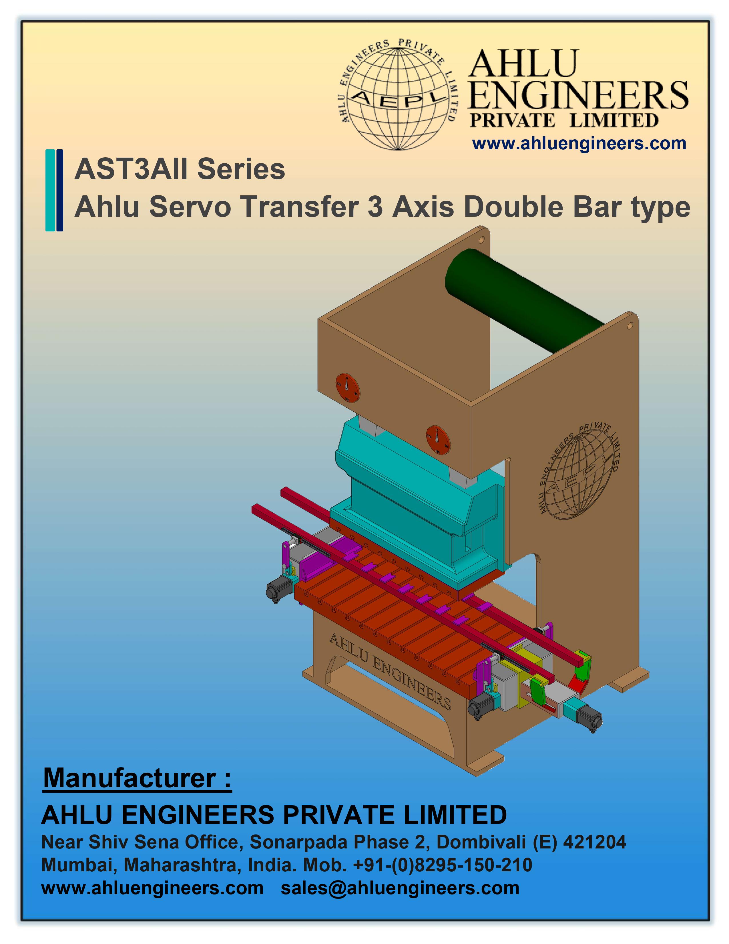
Ahlu Servo Transfer 3 Axis Double Bar type- AST3AII
Download Product Catalogue
Get comprehensive technical information, specifications, and usage guidelines for Ahlu Servo Transfer 3 Axis Double Bar type- AST3AII.
Free download • No spam • Instant access
Product Videos
Explore Our Premium Solutions
Our wide array of expertly designed automation solutions, tailored to enhance your manufacturing processes with precision and efficiency.
Ahlu Servo Transfer 2 Axis Double Bar type- AST2AII
Ahlu Servo Transfer 2 Axis Single Bar type- AST2AI
Ahlu Servo Roll Feeder type- ASRF Series
Ahlu Over Head Servo Transfer Robot - AOHST
Need a Custom Automation Solution?
Our experienced engineers specialize in designing tailored automation systems that perfectly match your unique manufacturing requirements. From concept to implementation, we deliver precision-engineered solutions that boost productivity and efficiency.
✓Expert Engineering Team
45+ years of automation experience
✓Industry Leading Innovation
Cutting Edge automation solutions for modern challenges
✓Complete Support
From design to maintenance & training
Our automation experts are here to help.